District heating is the term used to describe the supply of heat for heating buildings or properties and for production processes. The thermal energy is transported in a heat insulated pipe system, which is mainly laid underground, although overhead lines are also used in some cases.
Plastic jacket (KM) long-distance heat exchanger (Gammel Engineering)

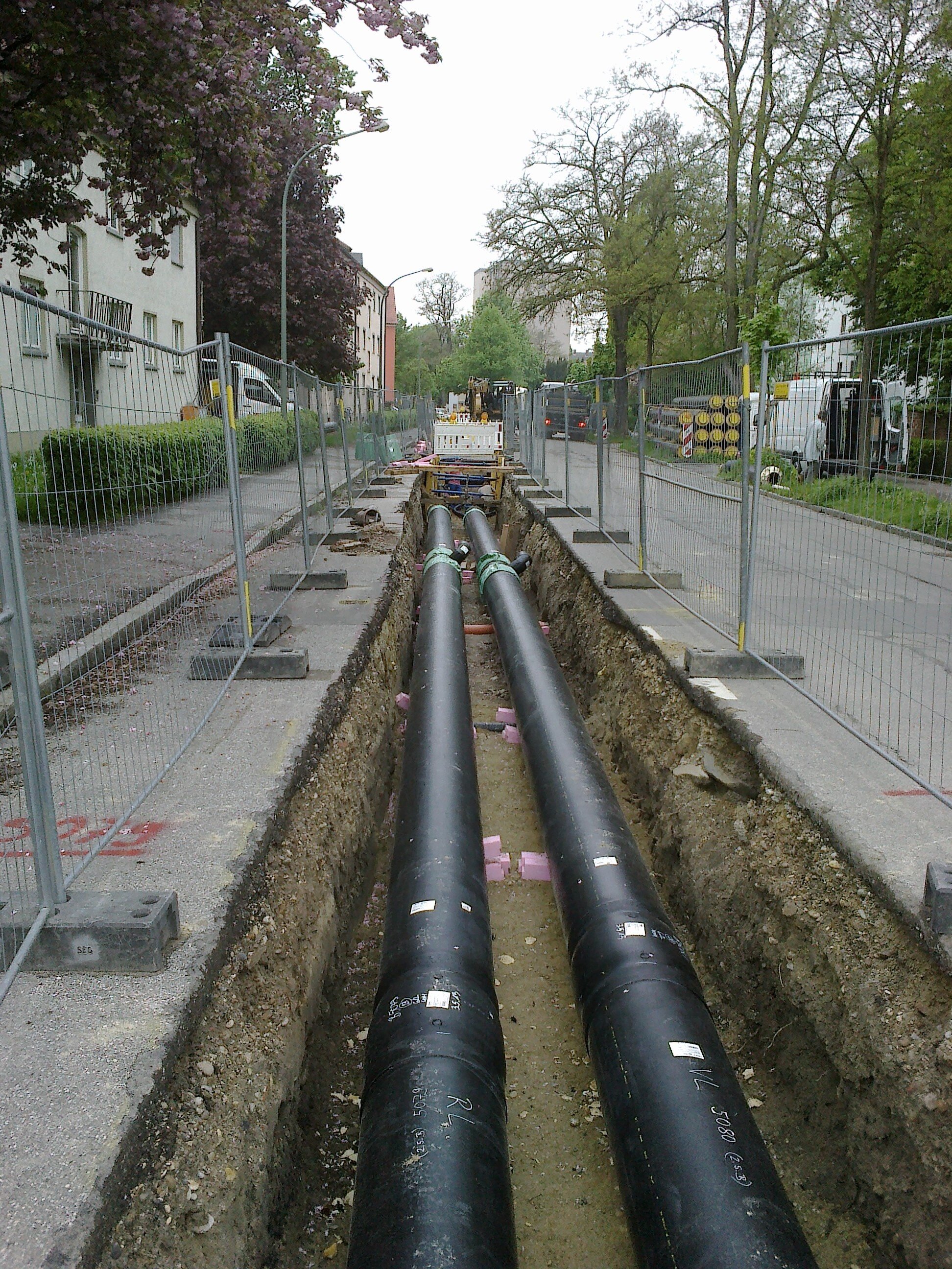
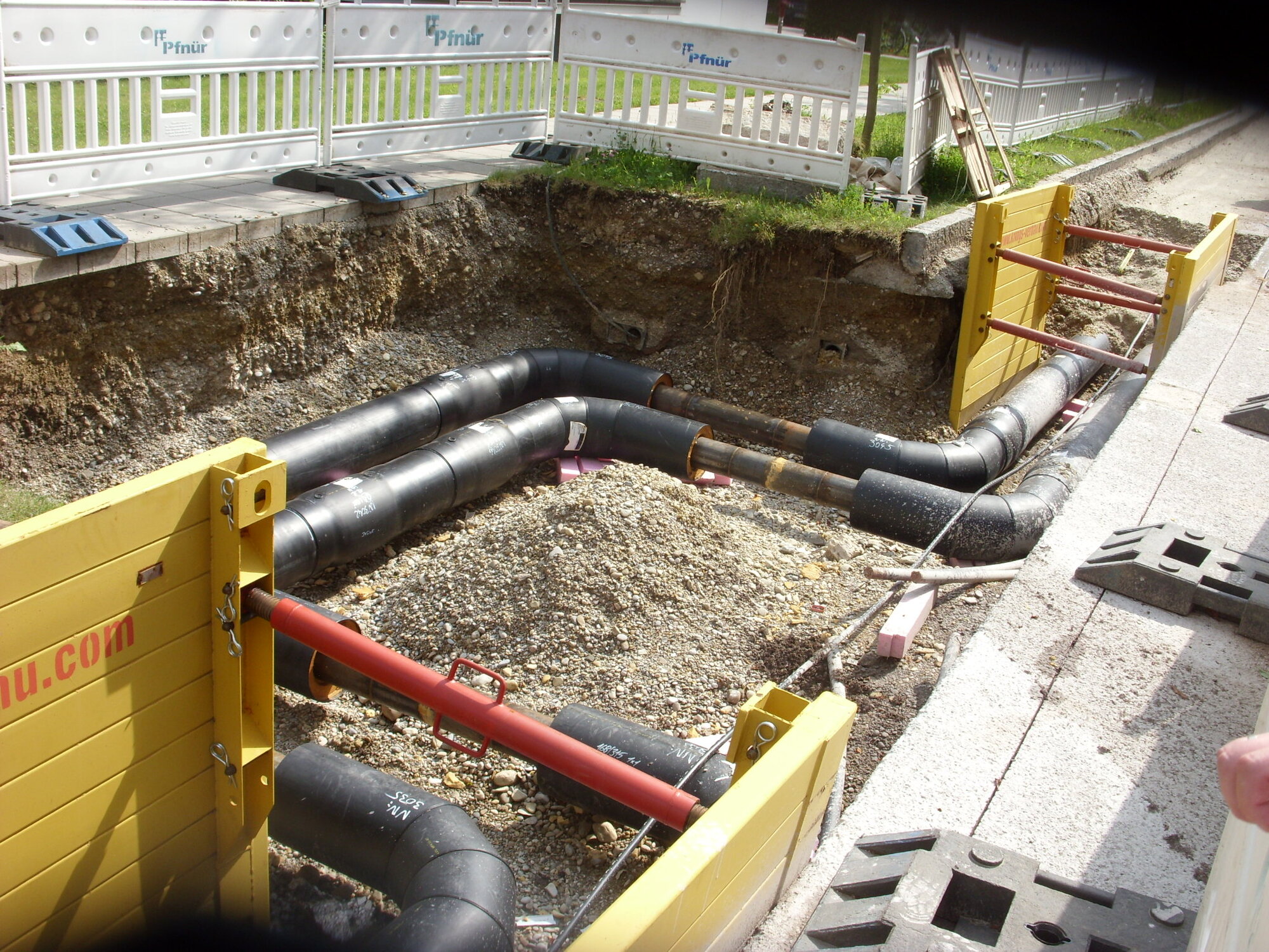
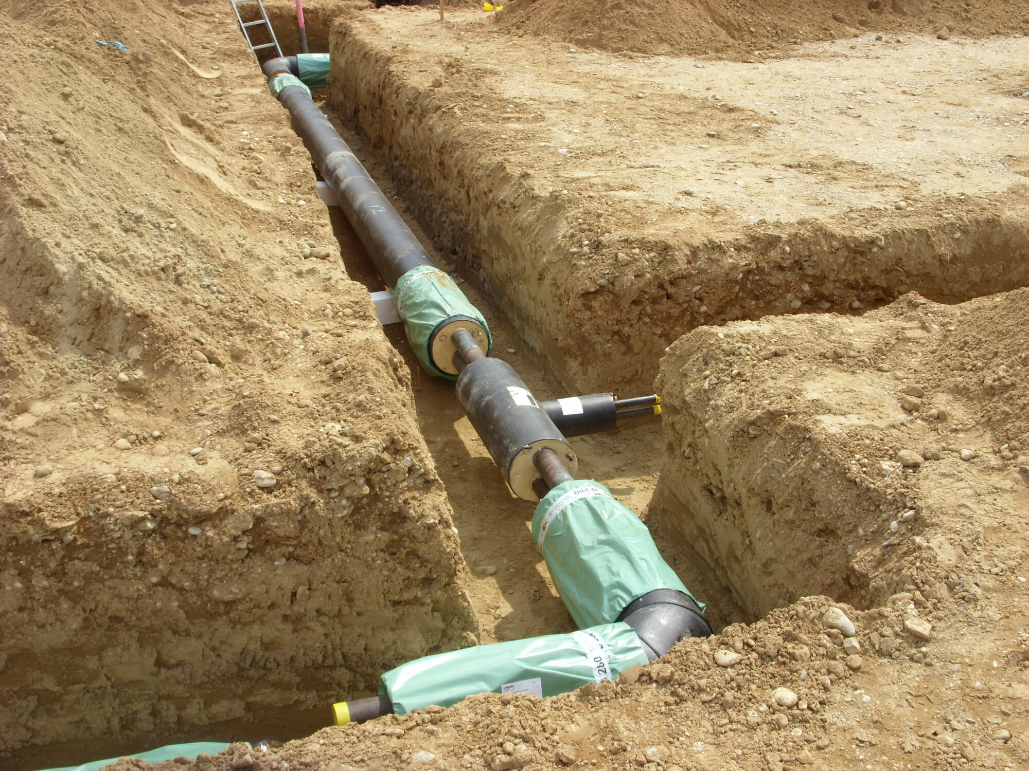
Laying plastic casing pipe (KM) in the pipe trench (Gammel Engineering)
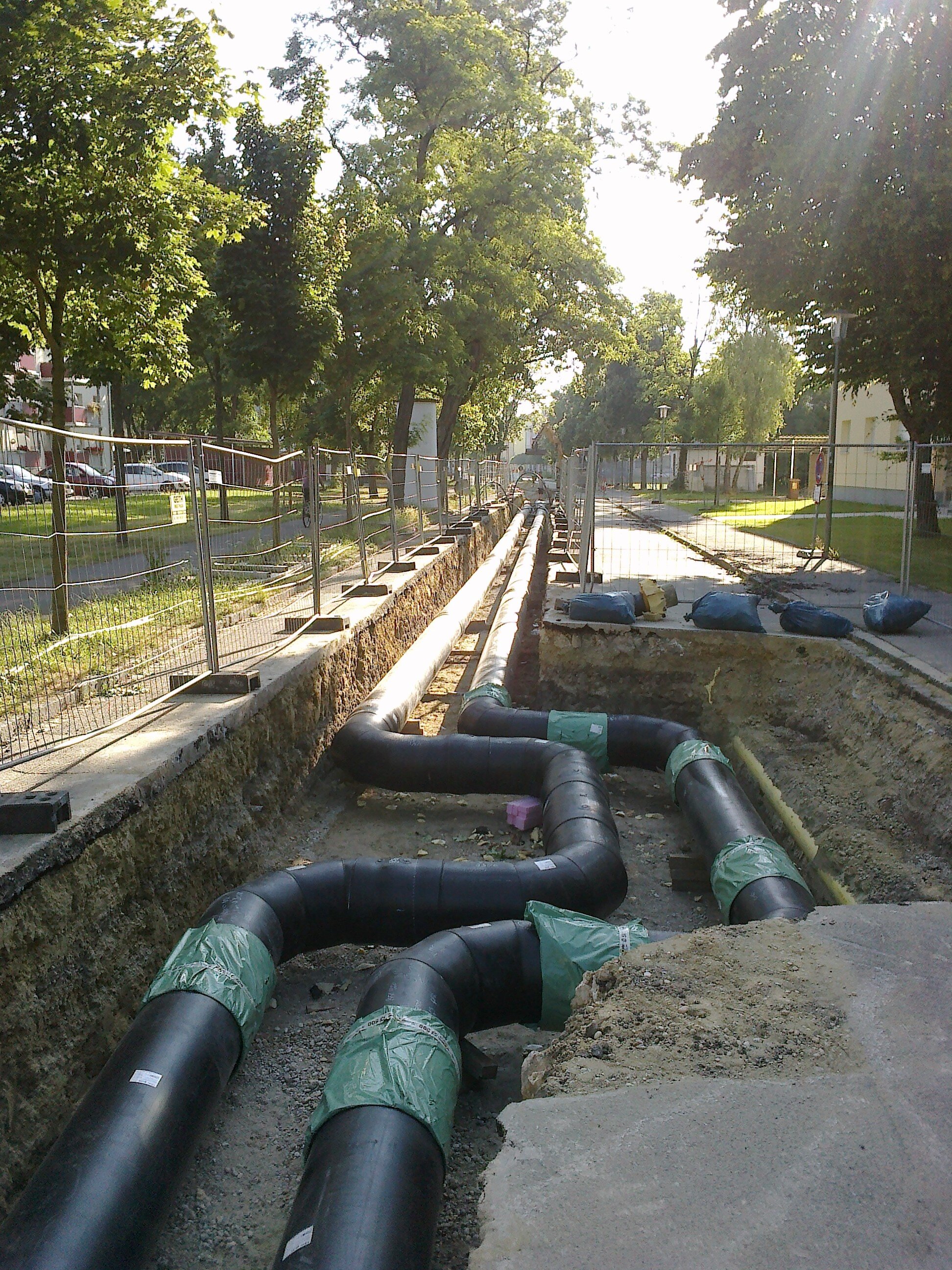
KM route with expansion bend (Gammel Engineering)
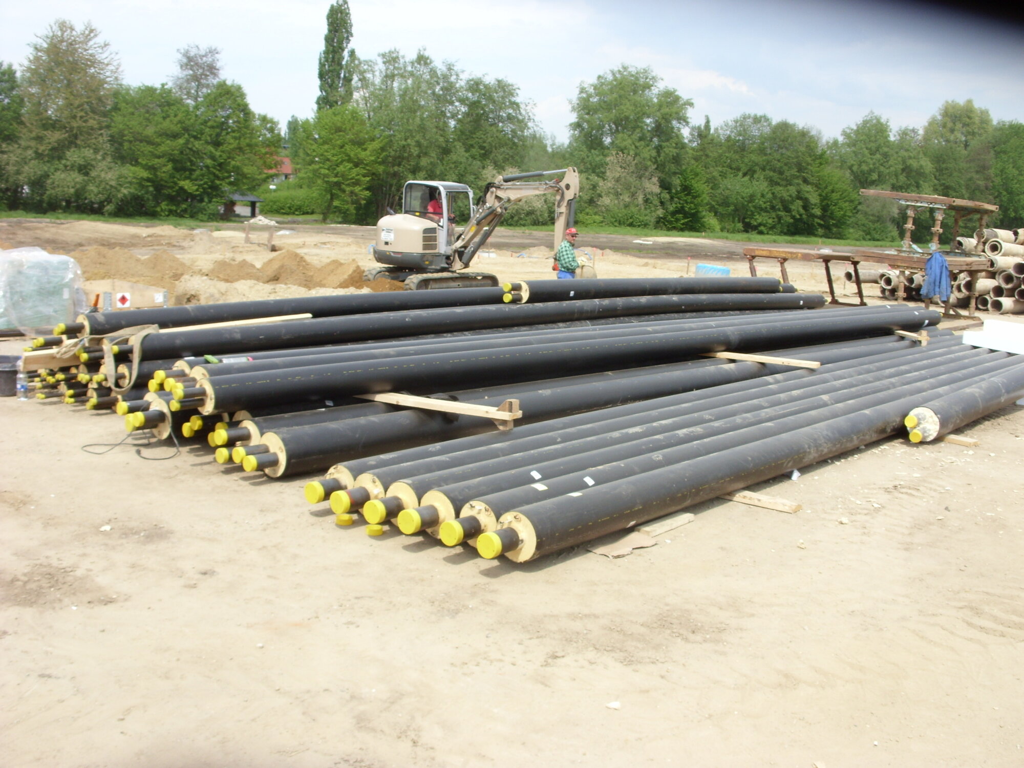
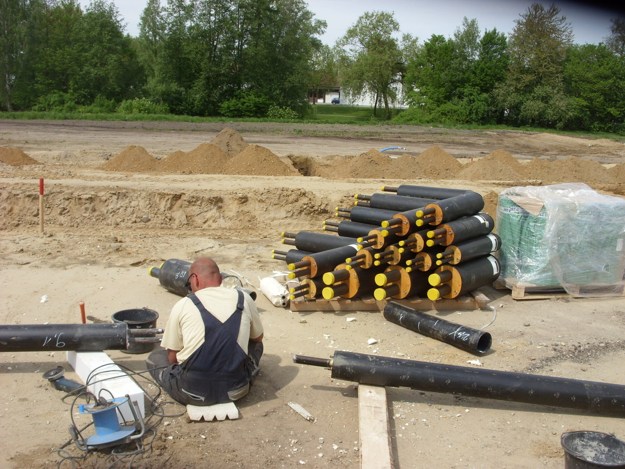
KM pipe store on the construction site (Gammel Engineering)
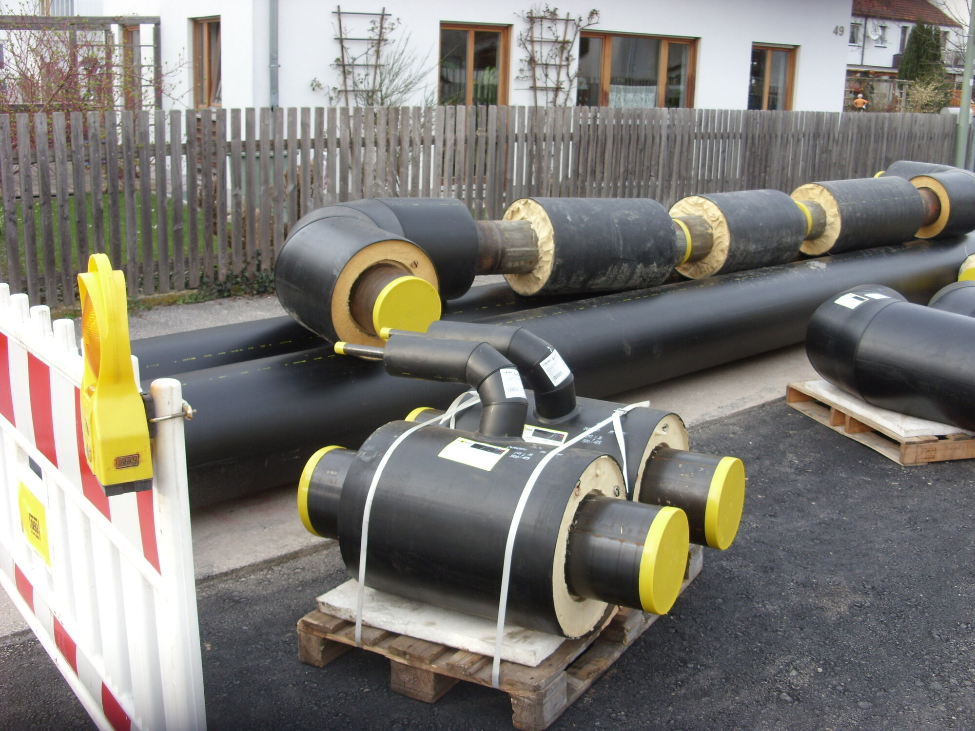
KM molds on the construction site (Gammel Engineering)
Mounting expansion bend (Gammel Engineering)
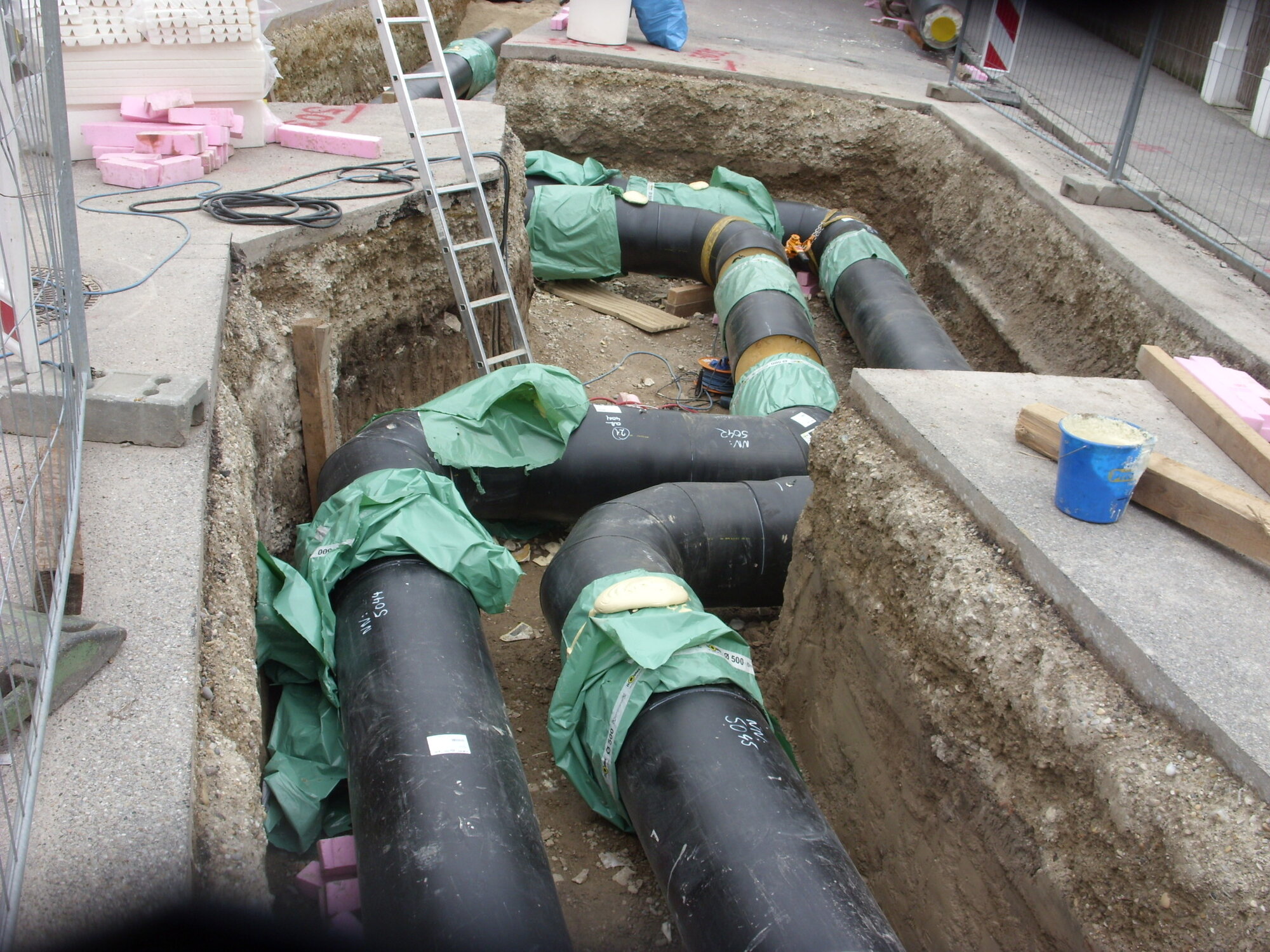
Expansion bend with directional change (Gammel Engineering)
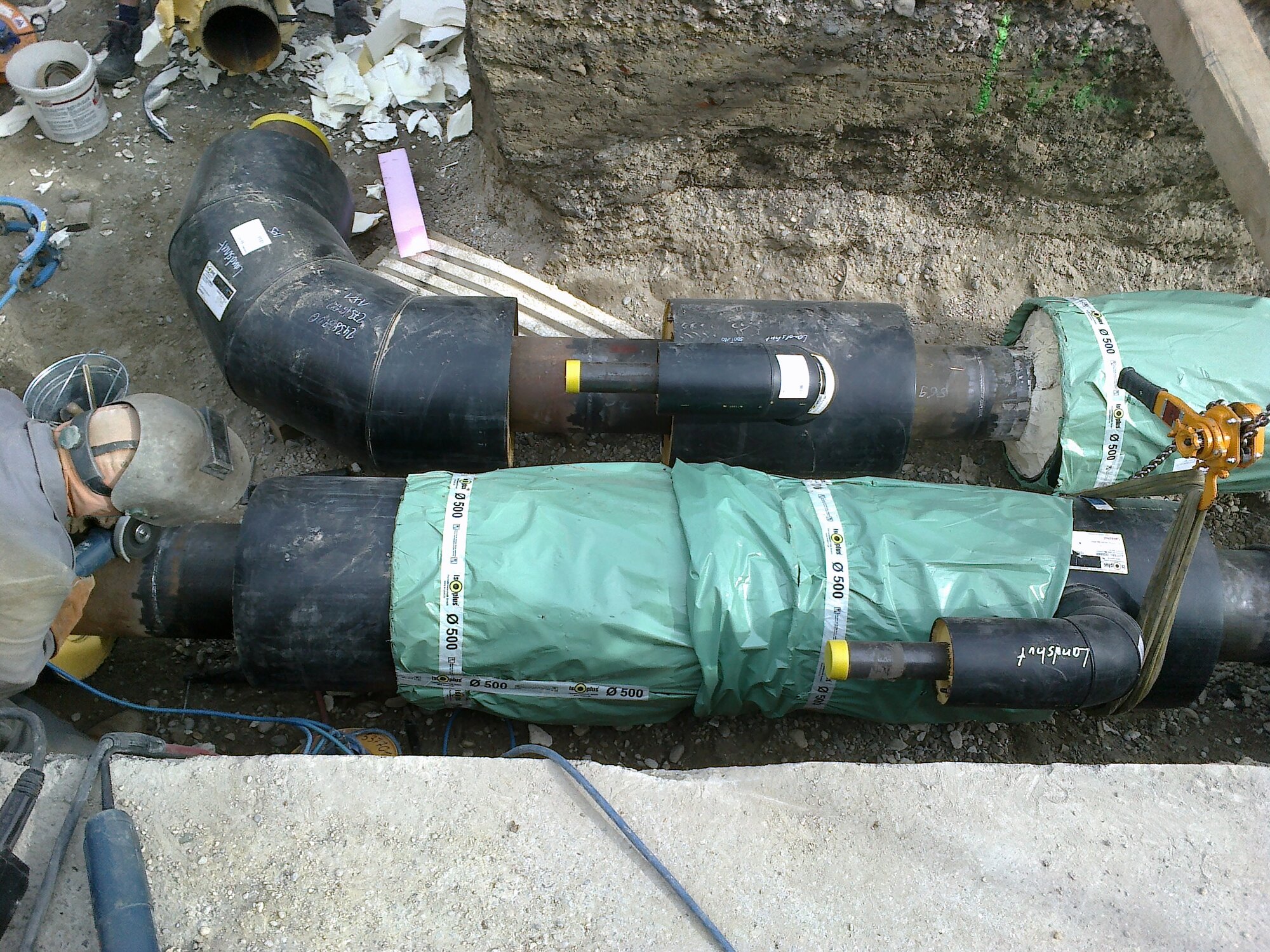
Assembly of the mold (Gammel Engineering)
Double-tube molded piece (Gammel Engineering)
Double pipe route with branch (Gammel Engineering)
District heating supplies residential, commercial and industrial buildings by routing the heat from the producer or collection point to the consumers. District heating is understood to mean the supply of entire towns or districts. The local supply of individual buildings, parts of buildings or small housing estates with their own heat generation is also referred to as local heating. Technically and legally, district heating is the correct term in all cases.
The umbrella association for district heating in Germany is AGFW Der Energieeffizienzverband fürme, Kälte und KWK e.V.As an independent, neutral and powerful energy efficiency association, the AGFW promotes the development and expansion of cogeneration (CHP) as well as district heating and cooling supply of all sizes on a national and international level.
The idea of using district heating on a larger scale and commercially emerged towards the end of the 19th century. By reducing the number of fireplaces in inner cities, the risk of fires was reduced and pollution from coal and ash was curbed. A key aspect is the possibility of increasing the efficiency of thermal power plants by extracting heat between the turbine stages using so-called cogeneration. With its large specific heat capacity, water is particularly suitable as a medium for heat transport. In the field of district heating, it is used in liquid form or in the form of steam. More recently, however, steam networks have increasingly been replaced by hot water networks, as their operation is less risky, among other things. The medium is conveyed in heat-insulated pipes in a continuous circuit. To prevent corrosion and hardness precipitation on the inner surfaces of the pipes, the water used in the circuit is at least softened
The pipes from the heat source to the heat sinks are referred to as the flow, those from the heat sinks back to the heat source as the return.
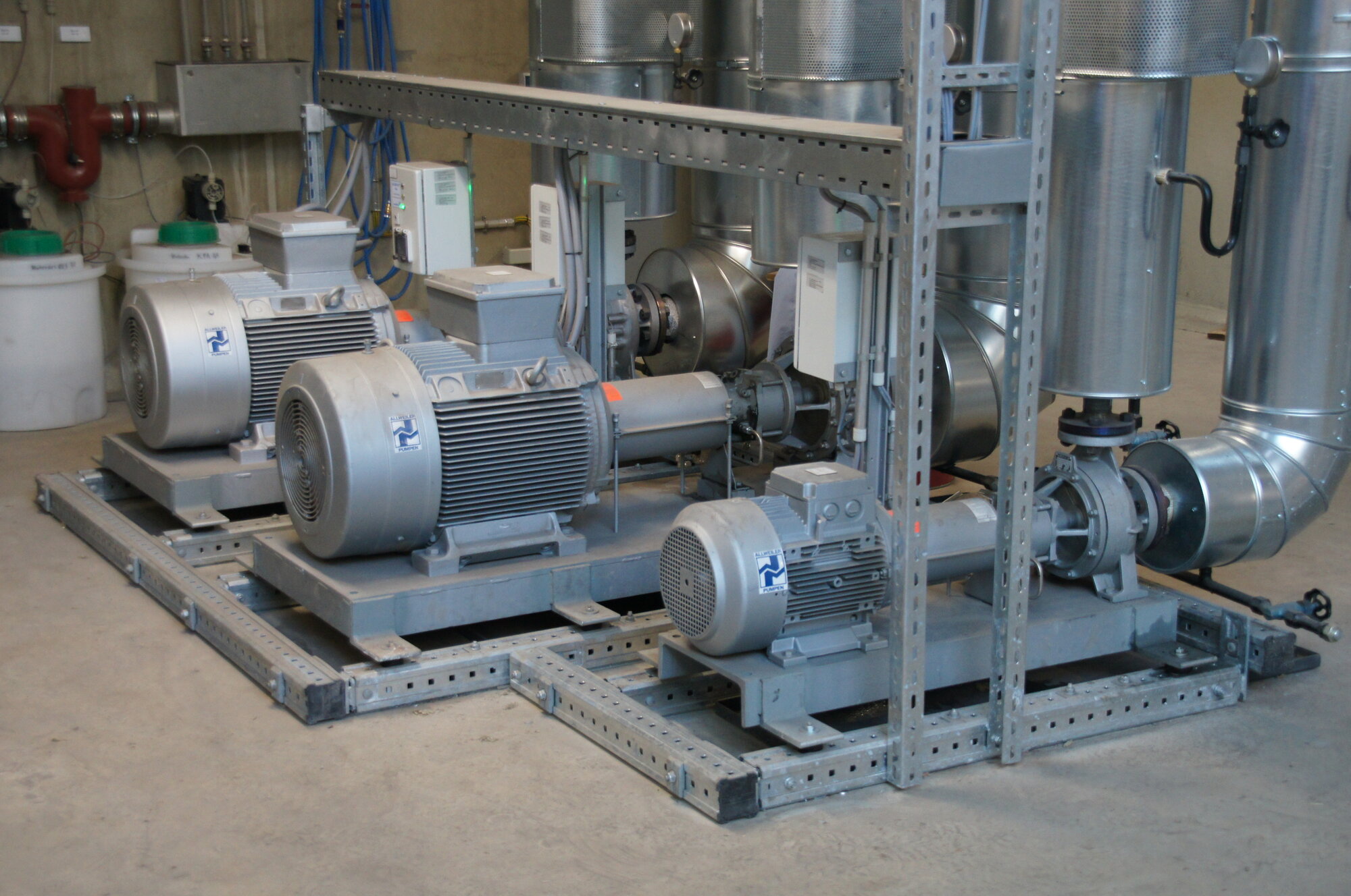
Remote heat pump station (Gammel Engineering)
The pipes in direct contact with the medium are referred to as service pipes. Depending on the medium temperature, required flow rate and static requirements, the piping systems used are plastic jacket composite pipes, steel jacket pipes, spiral ducts and various flexible pipe systems (composite pipe systems, pipe systems without composite). typical operating temperatures for the flow in a district heating network operated with hot water are 80-130°C at an operating pressure of 1.6-2.5 MPa (16-25 bar). In smaller district heating networks with lower flow temperatures of 70–90°C, lower operating pressures of 0.4–1.0MPa (4–10 bar) are also used. The heat is transferred to the consumer by means of a transfer station, the so-called compact station, which can consist of various components. In most cases, the district heating circuit is hydraulically separated from the consumer circuit by a heat exchanger; in a few cases (large consumers), the district heating circuit is connected directly. Particularly in modern, high-temperature insulated residential buildings, the design of the transfer station is not primarily based on the heating demand, but on the heat demand for hot water preparation. During hot water preparation, a hot water temperature of more than 60°C must be maintained to avoid contamination of the hot water system with legionella. Depending on requirements, three variants are available for hot water preparation:
- In the flow-through system, the hot water required is heated directly in the heat exchanger of the transfer station. This requires a correspondingly large heat exchanger with a correspondingly large district heating connection. However, the risk of contamination with legionella is very low and the return flow of the district heating water is reduced to a low temperature level. The flow-through system is suitable for consumers with a relatively constant hot water demand and for consumers with a very low district heating connection capacity anyway, as the transfer station cannot be designed to be as small as required within a technically feasible framework
- In the storage system, water is heated in a storage tank („the storage tank is charged“) and withdrawn from it as required. The district heating connection can be much smaller. This increases the risk of contamination with legionella, which requires special protective measures (regular thermal disinfection). In the worst case, the temperature level of the return flow of the district heating water can rise almost to the temperature in the hot water storage tank, which is an unfavorable operating condition. In addition, the amount of hot water available is limited by the volume of the cylinder. After withdrawing the available quantity, you have to wait until the cylinder has been recharged. Another disadvantage is the additional space required by the cylinder and the heat losses of the cylinder. Storage tank systems are suitable for consumers with highly fluctuating hot water requirements, such as individual homes. The storage tank charging system combines the flow system with the storage tank system. The flow-through system included is only designed for an average hot water demand, so the district heating connection can be smaller than with a pure flow-through system. Peak loads are covered by a hot water storage tank, which is charged during off-peak periods.
- Future energy Sauerlach
- Biowärme Aichach
- Biowärme Taufkirchen
- Natural energy Cham
- Hartenstein
- Natural energy Hersbruck
- Natural energy Bad Gögging
- Wärmeversorgung Arco / Moos
- ..
District heating is usually generated in combined heat and power plants with cogeneration (CHP), smaller cogeneration plants, in waste incineration plants or district heating plants. Natural gas, biogas, oil, wood and wood products, solar thermal energy, coal and waste oil in various compositions and forms of processing are used as fuel. In a few countries, e.g. Switzerland, district heating is also extracted from nuclear power plants. In Iceland, but also in Central Europe, district heating is generated in geothermal power plants. In Scandinavia, but also in parts of Germany and Austria, district heating is also supported by solar thermal power plants and is known as solar district heating. District heating can also be generated with electricity in an electrode boiler in times of favorable electricity prices (e.g. during peaks in the output of solar or wind power, when generation exceeds consumption). This technology, which is widely used in Denmark, was first implemented in Germany in spring 2013 by Stadtwerke Flensburg. As far as possible, waste heat from industrial operations, for example from refineries or steelworks, is also used as a heat source.
Due to the unavoidable heat loss over long distances even with very good heat transfer and the high investment costs for the pipe system, district heating is only suitable for densely built-up areas. District heating networks usually have star-shaped distribution structures with maximum pipe lengths of several tens of kilometers
The largest German district heating networks can be found in Berlin, Hamburg and Mannheim. Flensburg is one of the cities with the highest market share for district heating (90%). Flensburg was modeled on the German cities on the Baltic Sea, which have roughly the same density of district heating.
The municipality of Kaufering near Landsberg am Lech was a pioneer in the development of new housing estates in smaller towns and municipalities. Mayor Dr. Klaus Bühler, with the support of his local council, commissioned the Öko-Institut Freiburg to draw up an integrated energy concept for the Kaufering Nord development area back in 1991. The minimum insulation standard for the residential buildings was defined and implemented by the developers with the advice of the local authority. The engineering services for the construction of the heating network and the energy center with combined heat and power with natural gas CHP were entrusted to Gammel Engineering. The energy model was continued and, following the corresponding expansion of the district heating and connection of the German headquarters of HILTI, a biomass cogeneration plant with ORC technology was built.Other reference projects for heat networks in rural areas include
Sources :
Wikipedia http://de.wikipedia.org/wiki/Fernw%C3%A4rme
Gammel Engineering GmbH